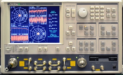
ANRITSU 37347D CALIBRATION and ANRITSU 37347D REPAIR

 
A calibration by Custom-Cal is performed by engineers with extensive OEM experience. We have the expertise and the necessary standards to perform the ANRITSU 37347D Calibration, onsite calibration may be available. We specialize in quick turnaround times and we can handle expedited deliveries upon request.

Need another Network Analyzer, SNA, VNA?
Shop for Comparable Products on our
 used Network Analyzer, SNA, VNA page or new Network Analyzer, SNA, VNA page

 
   ANRITSU 37347D   Description / Specification:    
ANRITSU 37347D 20 GHz Lightning D Vector Network Analyzer

The Anritsu 37347D 20 GHz Lightning D Vector Network Analyzer (VNA) is a high performance test tool designed to satisfy the growing needs of defense, satellite, radar, broadband communication, and high speed component markets. The 37347D VNA improve upon performance while providing a wider set of standard application features to better suit the needs of R&D engineers working on next generation designs. These new features, when combined with the ease of programming through helpful software utilities and faster data transfer over Ethernet, make it an equally valuable tool for manufacturing as well. This high performance two-port VNAs that include step attenuators, internal bias tees, a gain compression application. Multiple source control and set-on receiver mode allows the frequency of two sources and a receiver to be controlled without the need for an external controller. VNA Utilities is the ultimate solution for automated test software development. It includes fully functional application programs, re-usable calibration, set-up and data manipulation samples, and software development tools for creating custom applications. VNA Utilities includes applications such as the Capture Utility, which allows the user to extract data from the VNA in any of the supported formats (bitmap, S2P, plotter graphics, etc.). Specifications. Frequency Range: 40 MHz to 20 GHz. Port 1 Power, Typical: 10 dBm @ 0.04 GHz (max), 3 dBm @ 20 GHz. Noise Floor at Port 2 (RMS values – compensated for loss in available source power from test port cable connected between Port 1 and Port 2): -85 dBm @ 0.04 GHz, -103dBm @ 20 GHz, Max. -107 dBm @ 2 GHz. System Dynamic Range: 95 dB @ 0.04 GHz, 106 dB @ 20 GHz, Max. 115 dB @ 2 GHz. Measurement Parameters: S11, S21, S22, S12 (User-defined combinations of a1, a2, b1, and b2.). Domains: Frequency Domain, CW Draw, and optional High Speed Time (Distance) Domain. Data Points: 1601 maximum or N discrete data points where 2 <=N <=1601. IF Bandwidth: 10 kHz to 10 Hz. GPIB: 2 Ports, system GPIB and dedicated GPIB. Display: Color LCD, 8.5" diagonal. Option 1A Rack mount kit with handles only (no slides). Option 2A Time Domain (Distance) measurement capability. Option 4A External SCSI-2 hard disk drive compatibility. Option 7A Replaces K test port connectors with GPC-7 connectors. Option 7N Replaces K test port connectors with N(m) connectors. Option 7NF Replaces K test port connectors with N(f) connectors. Option 7S Replaces K test port connectors with 3.5 mm-(m) connectors. Option 15 Flexible test set.


Standard Calibration $800.00 *
Click on Logo for More Prices
*This is a Web introductory price for one calibration of the ANRITSU 37347D. Price does not in most cases include measurement performance data. Pricing does include NIST traceable calibration and issue of a calibration certificate and calibration label. Pricing may vary slightly due to volume and location of laboratory supporting calibration. Volume pricing may apply. On-site fees may apply depending on logistics, location and volume of work to be completed during the visit.


Related RF Terms and Definitions. For a complete list go to our  Terms and Definitions Page.

Averaging
Averaging is a mathematical process to reduce the variation in a measurement by summing the data points from multiple measurements and dividing by the number of points summed.

Jitter
Jitter in technical terms is the deviation in or displacement of some aspect of the pulses in a high-frequency digital signal. Jitter is the time variation of a periodic signal in electronics and telecommunications, often in relation to a reference clock source. Jitter may be observed in characteristics such as the frequency of successive pulses, the signal amplitude, or phase of periodic signals. Jitter is a significant, and usually undesired, factor in the design of almost all communications links (e.g., USB, PCI-e, SATA, OC-48). In clock recovery applications it is called timing jitter.

Pulse Power
Pulse Power, the energy transfer rate is averaged over the pulse width. Pulse width is considered to be the time between the 50 percent risetime/falltime amplitude points. Pulse power averages out any aberrations in the pulse envelope such as overshoot or ringing.


Please contact us for your ANRITSU 37347D CALIBRATION and/or ANRITSU 37347D 20 GHz Lightning D Vector Network Analyzer REPAIR

I'm interested in: 
Calibration Type (Select one):


Repair Information:
 Serial Number:

 Is there any physical damage?  
 If yes, describe:


What is the description of the problem?

How/when did the problem start?


 (*) Required Fields    For formal quote please fill in all fields.
Company:
From (Email):*
Contact Name:*
Country:*
Address 1:
Address 2:
City:
State/Territory/Province: *
Zip/Postal Code:
Phone:*

Comment: