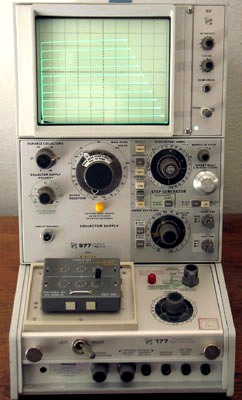
TEKTRONIX 577D1-177 CALIBRATION and TEKTRONIX 577D1-177 REPAIR

 
A calibration by Custom-Cal is performed by engineers with extensive OEM experience. We have the expertise and the necessary standards to perform the TEKTRONIX 577D1-177 Calibration, onsite calibration may be available. We specialize in quick turnaround times and we can handle expedited deliveries upon request.


   TEKTRONIX 577D1-177   Description / Specification:    
TEKTRONIX 577D1-177 Non-programmable Curve Tracer System

The Tektronix 577/177 is a non-programmable Curve Tracer System consits of a 577 Curve-Tracer Mainframe and a 177 Test Fixture. It is designed for testing semiconductor devices at power levels up to 100 Watts. Maximum continuous current is 10 amps (20 amps in pulsed mode). The 577's storage CRT may be used to overlay the characteristic curves of one device on top of the stored characteristics of another. Dot displays (generated during high-current pulsed testing or during very low-current testing under dc condItions) can be transformed into complete characteristic curves by simply moving them across the CRT while in the storage mode. Collector Supply Modes/Polarity: Norm; AC (at line frequency); positive or negative full-wave rectified ac. DC: Positive or negative dc. Collector Supply Voltage 6.5V (10A cont.) to 1600V (0.04A cont.). Collector Supply Series Resistance: From 0.12 ohm to 8 Mohm in 14 steps, all within 15%, ±0.1 ohm. Peak Power Limit Setting: 100, 30, 9, 2.3, 0.6, and 0.15 W. Step Generator Current Mode:Step/Offset Amplitude Range: 5 nA/step (with X0.1 Mult) to 200 rnA/step, 1-2-5 sequence. Maximum Current (Steps and Aiding Offset): X20 amplitude setting, except X10 (2A) at 200 rnA/step and X15 (1.5 A) at 100 rnA/step. Maximum Voltage (Steps and Aiding Offset): At least 7 V. Maximum Opposing Offset Current: X10 amplitude setting or 10 rnA, whichever is less. Maximum opposing voltage is limited at 1 to 5 V. Step Generator Voltage Mode: Step/Offset Amplitude Range: 5 mV/step (with X0.1 Mult) to 2 V/step, 1-2-5 sequence. Maximum Voltage (Steps and Aiding Offset): 20 times amplitude-switch setting. Maximum Current: At least 100 rnA at 0 V. Short-Circuit Current Limiting: Not more than 200 rnA. Maximum Opposing Offset Voltage: X10 amplitude-switch setting. Maximum Opposing Current: Limited between 10 and 20 rnA (derating to 0 rnA at 20 V). Step Generator Accuracy Incremental: Within 2% between steps. Absolute: Within 3% of total output or amplitude setting, whichever is greater. Within 4% with X0.01 mult. Offset Multiplier: Continuously variable from 0 to X10 the amplitude setting, either aiding or opposing the step polarity. Vertical-Deflection Factor: Collector Current: 2 nA to 2 A/div, 28 steps in 1-2-5 sequence (0.2 nA to 0.2 A/div with X10 magnification). Horizontal-Deflection Factor: Collector Volts: 50 mV to 200 V/div, 12 steps in 1-2-5 sequence (5 mV to 20 V/div with X10 magnification). Base Volts: - 50 mV to 2 V/div, 6 steps in 1-2-5 sequence (5 mV to 0.2 V/div with X10 magnification). Step Generator: 1 step/div (0.1 step/div with X10 magnification).


Standard Calibration $700.00 *
Click on Logo for More Prices
*This is a Web introductory price for one calibration of the TEKTRONIX 577D1-177. Price does not in most cases include measurement performance data. Pricing does include NIST traceable calibration and issue of a calibration certificate and calibration label. Pricing may vary slightly due to volume and location of laboratory supporting calibration. Volume pricing may apply. On-site fees may apply depending on logistics, location and volume of work to be completed during the visit.


Related Bench Equipment Terms and Definitions. For a complete list go to our  Terms and Definitions Page.

Channel Bandwidth
Channel Bandwidth is the bandwidth over which power is measured. This is usually the bandwidth in which almost all of the power of a signal is contained.

Jitter
Jitter in technical terms is the deviation in or displacement of some aspect of the pulses in a high-frequency digital signal. Jitter is the time variation of a periodic signal in electronics and telecommunications, often in relation to a reference clock source. Jitter may be observed in characteristics such as the frequency of successive pulses, the signal amplitude, or phase of periodic signals. Jitter is a significant, and usually undesired, factor in the design of almost all communications links (e.g., USB, PCI-e, SATA, OC-48). In clock recovery applications it is called timing jitter.

Overshoot
Overshoot is the distortion that follows a major transition; the difference between the peak power point and the pulse-top amplitude computed as a percentage of the pulse-top amplitude.

Rise Time
Rise time refers to the time required for a signal to change from a specified low value to a specified high value, usually 10 and 90 percent of pulse-top amplitude (vertical display is linear power).


Please contact us for your TEKTRONIX 577D1-177 CALIBRATION and/or TEKTRONIX 577D1-177 Non-programmable Curve Tracer System REPAIR

I'm interested in: 
Calibration Type (Select one):
Repair Information:
 Serial Number:

 Is there any physical damage?  
 If yes, describe:


What is the description of the problem?

How/when did the problem start?


 (*) Required Fields    For formal quote please fill in all fields.
Company:
From (Email):*
Contact Name:*
Country:*
Address 1:
Address 2:
City:
State/Territory/Province: *
Zip/Postal Code:
Phone:*

Comment: