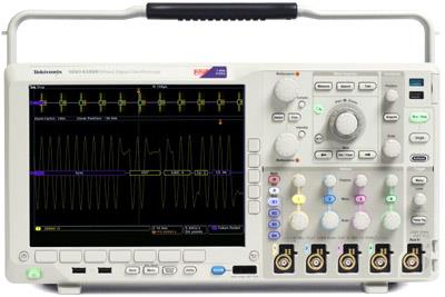
TEKTRONIX MSO4104B CALIBRATION and TEKTRONIX MSO4104B REPAIR

 
A calibration by Custom-Cal is performed by engineers with extensive OEM experience. We have the expertise and the necessary standards to perform the TEKTRONIX MSO4104B Calibration, onsite calibration may be available. We specialize in quick turnaround times and we can handle expedited deliveries upon request.

Need another Oscilloscope?
Shop for Comparable Products on our
 used Oscilloscope page

 
   TEKTRONIX MSO4104B   Description / Specification:   Spec Sheet 
TEKTRONIX MSO4104B 4+16 Ch 1 GHz, 5 GS/s, Mixed Signal Oscilloscope

The Tektronix MSO4104B Mixed Signal Oscilloscope can analyze up to 20 analog and digital signals with a single instrument to quickly find and diagnose problems in complex designs. Bandwidths up to 1 GHz and a minimum of 5x oversampling on all channels ensure you have the performance you need to see fast-changing signal details. To capture long windows of signal activity while maintaining fine timing resolution, the MSO4104B offers a deep record length of 20M points standard on all channels. With Wave Inspector® controls for rapid waveform navigation, automated serial and parallel bus analysis, limit and mask testing, and automated power analysis

Vertical System Analog Channels
Input Channels: 4.
Analog Bandwidth (-3 dB) 5 mV/div -1 V/div: 1 GHz.
Calculated Rise Time 5 mV/div (typical): 350 ps.
Hardware Bandwidth Limits: 20 MHz or 250 MHz.
Input Coupling: AC, DC.
Input Impedance 1 MΩ: ±1%, 50 Ω ±1%.
Input Sensitivity, 1 MΩ: 1 mV/div to 10 V/div.
Input Sensitivity, 50 Ω: 1 mV/div to 1 V/div.
Vertical Resolution: 8 bits (11 bits with Hi Res).
Max Input Voltage, 1 MΩ: 300 VRMS CAT II with peaks ≤ ±425 V.
Max Input Voltage, 50 Ω: 5 VRMS with peaks ≤ ±20 V (DF ≤ 6.25%).
DC Gain Accuracy: ±1.5%, derated at 0.10%/°C above 30 °C.
Channel-to-Channel Isolation: Any two channels at equal vertical scale ≥100:1 at ≤100 MHz and ≥30:1 at >100 MHz up to the rated bandwidth.

Horizontal System Analog Channels
Maximum Sample Rate (All channels): 5 GS/s.
Maximum Record Length (All channels): 20M.
Duration at Highest Sample Rate (All channels): 4 ms.
Time Base Range: 400 ps to 1,000 s.
Time Base Delay Time Range: -10 divisions to 5000 s.
Channel-to-Channel Deskew Range: ±125 ns.
Time Base Accuracy: ±5 ppm over any ≥1 ms interval.

Vertical System Digital Channels
Input Channels: 16 Digital (D15 - D0).
Thresholds: Per-channel Thresholds.
Threshold Selections: TTL, CMOS, ECL, PECL, User Defined.
User-defined Threshold Range: ±40 V.
Maximum Input Voltage: ±42 Vpeak.
Threshold Accuracy: ±(100 mV + 3% of threshold setting).
Input Dynamic Range: 30 Vp-p ≤200 MHz, 10 Vp-p >200 MHz.
Minimum Voltage Swing: 400 mV.
Probe Loading: 100 kΩ in parallel with 3 pF.
Vertical Resolution: 1 bit.

Horizontal System Digital Channels
Maximum Sample Rate (Main): 500 MS/s (2 ns resolution).
Maximum Record Length (Main): 20M points.
Maximum Sample Rate (MagniVu): 16.5 GS/s (60.6 ps resolution).
Maximum Record Length (MagniVu): 10k points centered around the trigger.
Minimum Detectable Pulse Width: 1 ns.
Channel-to-Channel Skew: 200 ps.


Standard Calibration $240.00 *
Click on Logo for More Prices
*This is a Web introductory price for one calibration of the TEKTRONIX MSO4104B. Price does not in most cases include measurement performance data. Pricing does include NIST traceable calibration and issue of a calibration certificate and calibration label. Pricing may vary slightly due to volume and location of laboratory supporting calibration. Volume pricing may apply. On-site fees may apply depending on logistics, location and volume of work to be completed during the visit.


Related Bench Equipment Terms and Definitions. For a complete list go to our  Terms and Definitions Page.

dBc
dBc (decibels relative to the carrier) is the power ratio of a signal to a carrier signal, expressed in decibels. If the dBc figure is positive, then the relative signal strength is greater than the carrier signal strength. If the dBc figure is negative, then the relative signal strength is less than carrier signal strength.

Load Regulation
Load regulation is the capability to maintain a constant voltage (or current) level on the output channel of a power supply despite changes in the supply's load (such as a change in resistance value connected across the supply output).

Power Linearity
When changing the power level and measuring the differences (in dB) between actual and displayed power levels, the power linearity is ± half the span (in dB) between the maximum and the minimum value of all differences.

Settling Time
Settling time of an output device is the time elapsed from the application of an ideal instantaneous step input to the time at which the amplifier output has entered and remained within a specified error band, usually symmetrical about the final value.


Please contact us for your TEKTRONIX MSO4104B CALIBRATION and/or TEKTRONIX MSO4104B 4+16 Ch 1 GHz, 5 GS/s, Mixed Signal Oscilloscope REPAIR

I'm interested in: 
Calibration Type (Select one):


Repair Information:
 Serial Number:

 Is there any physical damage?  
 If yes, describe:


What is the description of the problem?

How/when did the problem start?


 (*) Required Fields    For formal quote please fill in all fields.
Company:
From (Email):*
Contact Name:*
Country:*
Address 1:
Address 2:
City:
State/Territory/Province: *
Zip/Postal Code:
Phone:*

Comment: