|
|
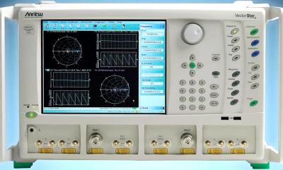
The Anritsu MS4647A 70 GHz VectorStar Vector Network Analyzer, 2-port, V(male) offers a new level of performance for device modeling engineers struggling to accurately and reliably characterize their devices, for R&D engineers pushing the last fraction of a dB out of their state-of-the-art designs, and for the manufacturing engineer trying to maximize throughput without sacrificing accuracy. Anritsu's MS4647A VNA offers the broadest coverage in a single instrument, 10 MHz to 70 GHz. The additional two decades at the low end are even more impressive than the guaranteed 70 GHz coverage on the high end, for better device modeling without having to switch to another RF VNA. The industry leading 100 dB dynamic range at 70 GHz. Specifications. Frequency Range: 10 MHz to 70 GHz. System Dynamic Range at Ports 1 or 2: 122 dB (0.01 to 2.5 GHz), 116 dB (2.5 to 5 GHz), 115 dB (5 to 20 GHz), 116 dB (20 to 38 GHz), 115 dB (38 to 50 GHz), 107 dB (50 to 65 GHz). Receiver Dynamic Range at Ports 1 or 2: 120 dB (0.01 to 50 GHz), 117 dB (50 to 65 GHz). Receiver Compression at Ports 1 or 2: 10 dBm (10 MHz to 70 GHz). Noise Floor: -110 dBm (0.01 to 50 GHz), -107 dBm (50 to 65 GHz). Power Range: +12 to –25 dBm (0.01 to 2.5 GHz), +6 to –20 dBm (2.5 to 5 GHz), +6 to –25 dBm (20 to 38 GHz), +5 to –25 dBm (38 to 50 GHz), 0 to –25 dBm (50 to 65 GHz). Output Default Power: -3 dBm. Power Accuracy: ± 1.5 dB (0.01 to 40 GHz), ± 3.0 dB (40 to 67 GHz). Power Linearity: ± 1.0 dB (0.01 to 67 GHz). Frequency Resolution: 1 Hz. Frequency Accuracy: ± 5 x 10^-7 Hz/Hz (at time of calibration). Typical 20 µs/point is achieved in true swept mode, with 25,000 points. 2-Port Measurements: S11, S21, S22, S12, and any user-defined combination of a1, a2, b1, b2, and 1. IF Bandwidth: 1, 3, 10, 30, 100, 300 Hz; 1, 3, 10, 30, 100, and 300 kHz; 1 MHz. GPIB Ports: GPIB Port (Talker/Listener), GPIB Port (Dedicated Controller). Options. 002 - Time Domain with advanced capabilities. 004 - Additional Solid State Drive (SSD), Serial-ATA. 007 - Receiver Offset with Multiple Source Control for frequency-translated measurements. 041 - Noise Figure (Option 51, 61 or 62 required). 051 - Direct Access Loops for total measurement flexibility. 061 - Active Measurement Suites with 2 attenuators. 062 - Active Measurement Suites with 4 attenuators. 070 - 70 kHz Low-end Frequency Extension. 080 - Modular Broadband connection capability. 081 - Modular Broadband connection capability. 082 - Milllimeter Wave Interface. 083 - Milllimeter Wave Interface.
|