BERKELEY NUCLEONICS CORPORATION 1105 CALIBRATION and BERKELEY NUCLEONICS CORPORATION 1105 REPAIR

 
A calibration by Custom-Cal is performed by engineers with extensive OEM experience. We have the expertise and the necessary standards to perform the BERKELEY NUCLEONICS CORPORATION 1105 Calibration, onsite calibration may be available. We specialize in quick turnaround times and we can handle expedited deliveries upon request.

Need another Frequency Counter? Shop for Comparable Products on our   new Frequency Counter page

 
For Sale New, List Price $1,940.00   BERKELEY NUCLEONICS CORPORATION 1105   Description / Specification:   Spec Sheet 
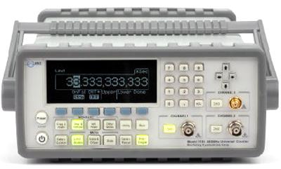
BERKELEY NUCLEONICS CORPORATION 1105 400 MHz Universal Frequency Counter

The Berkeley Nucleonics 1105 400 MHz Universal Frequency Counter has 12 digits of frequency resolution and 40 ps of time interval resolution. The real-time DSP front -end facilitates faster measurement throughput. It includes a RF Channel 3 with a range from 375 MHz to 6GHz and standard Channels 1 & 2 from 1 mHz to 400 MHz. Up to 20 frequently-used setups may be stored in memory.
The 1105 features include Frequency & Ratio (11 digits/sec.) , Time interval , Period (2.5 ns to 1000s) , Duty Cycle, Pulse Width, Rise/Fall Time, Peak Volts (100 Hz~300 MHz) , Phase, Totalize, with a time base temperature stability of < 1 PPM and aging rate of < 2 PPM per year. We can also measure the peak voltage of incoming waveforms as well.
Specifications.

Channel 1 & 2 Input.
DC Coupled: 1 mHz to 400 MHz.
AC Coupled: 200 KHz to 400 MHz (50 Ω), 30 Hz to 400 MHz (1 M Ω).
FM Tolerance: 25%.

Voltage Range and Sensitivity.
1 mH to 225 MHz: 20 mVrms to ±5 V ac + dc (Medium and High), 25 mVrms to ±5 V ac + dc (Low).
225 MHz to 400 MHz: 30 mVrms to ±5 V ac + dc.
400 MHz to 450 MHz: 40 mVrms to ±5 V ac + dc.

Voltage Range and Sensitivity (Single-Shot Pulse).
1.5ns to 10ns Pulse Width: 80 mVpp to 10 Vpp, (150 mVpp with optional rear connectors).
>10 ns Pulse Width: 50 mVpp to 10 Vpp, (150 mVpp with optional rear connectors).

Trigger Level(ATT x 1).
Range: ±5.125 V.
Accuracy: ±(15 mV + 1% of trigger level).
Resolution: 2.5 mV.
ATT x 10: Range X 10.
Trigger Slope: Positive or Negative.

Damage Level.
DC~400 MHz 50 Ω: 12 Vrms.
0 to 3.5 kHz, 1 M Ω: 350 V dc + ac pk.
3.5 kHz to 100 KHz, 1 M Ω: 350 V dc + ac pk linearly derated to 12 Vrms.
100 KHz to 400 MHz, 1 M Ω: 12 Vrms.

Measurement.
Frequency, Period: 1 mHz to 400 MHz (2.5 ns to 1000 s).
Channel 1 and 2 Trigger: Default setting is Auto Trigger at 50%.
Channel 1 and 2 “Auto” Gate Time: 0.1 sec.
STD CH 3: 375 MHz to 6 GHz (0.166 ns to 2.6 ns).
Frequency Ratio: CH 1/ CH 2, CH 1/ CH 3, CH 2/ CH 1, CH 3/ CH1 (Measurement is specified over the full signal range of each input).
Time Interval: Measurement is specified over the full signal ranges of Channels 1 and 2, the width of the pulse must be greater than 1 ns, frequency range to 300 MHz.
Time Interval Results Range: -0.5 ns to 10E+5 s.
Time Interval Resolution: 40 ps.


Standard Calibration $405.00 *
*This is a Web introductory price for one calibration of the BERKELEY NUCLEONICS CORPORATION 1105. Price does not in most cases include measurement performance data. Pricing does include NIST traceable calibration and issue of a calibration certificate and calibration label. Pricing may vary slightly due to volume and location of laboratory supporting calibration. Volume pricing may apply. On-site fees may apply depending on logistics, location and volume of work to be completed during the visit.


Related Bench Equipment Terms and Definitions. For a complete list go to our  Terms and Definitions Page.

Channel Bandwidth
Channel Bandwidth is the bandwidth over which power is measured. This is usually the bandwidth in which almost all of the power of a signal is contained.

Jitter
Jitter in technical terms is the deviation in or displacement of some aspect of the pulses in a high-frequency digital signal. Jitter is the time variation of a periodic signal in electronics and telecommunications, often in relation to a reference clock source. Jitter may be observed in characteristics such as the frequency of successive pulses, the signal amplitude, or phase of periodic signals. Jitter is a significant, and usually undesired, factor in the design of almost all communications links (e.g., USB, PCI-e, SATA, OC-48). In clock recovery applications it is called timing jitter.

Overshoot
Overshoot is the distortion that follows a major transition; the difference between the peak power point and the pulse-top amplitude computed as a percentage of the pulse-top amplitude.

Rise Time
Rise time refers to the time required for a signal to change from a specified low value to a specified high value, usually 10 and 90 percent of pulse-top amplitude (vertical display is linear power).


Please contact us for your BERKELEY NUCLEONICS CORPORATION 1105 CALIBRATION and/or BERKELEY NUCLEONICS CORPORATION 1105 400 MHz Universal Frequency Counter REPAIR

I'm interested in: 
Calibration Type (Select one):
Repair Information:
 Serial Number:

 Is there any physical damage?  
 If yes, describe:


What is the description of the problem?

How/when did the problem start?


 (*) Required Fields    For formal quote please fill in all fields.
Company:
From (Email):*
Contact Name:*
Country:*
Address 1:
Address 2:
City:
State/Territory/Province: *
Zip/Postal Code:
Phone:*

Comment: