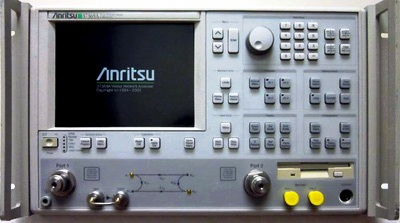
ANRITSU 37397A REPAIR and ANRITSU 37397A CALIBRATION

The ANRITSU 37397A is currently in stock and available for purchase on our  Sales Page
It is also available for immediate rental.
Custom-Cal has a high success rate in the repair of the ANRITSU 37397A. A calibration by Custom-Cal is performed by engineers with extensive OEM experience. We have the expertise and the necessary standards to perform the ANRITSU 37397A Calibration, onsite calibration may be available. We specialize in quick turnaround times and we can handle expedited deliveries upon request.

Need another Network Analyzer, SNA, VNA?
Shop for Comparable Products on our
 used Network Analyzer, SNA, VNA page or new Network Analyzer, SNA, VNA page

 
   ANRITSU 37397A   Description / Specification:    
ANRITSU 37397A 65 GHz Vector Network Analyzer

The Anritsu 37397A is a microprocessor controlled Vector Network Analyzer. It integrates a synthesized source, S-parameter test set and tuned receiver into a single compact package that is ideal for bench-top testing. It provides: 40 MHz to 65 GHz, Fast Sweeping Synthesized Source, Auto Reversing Test Set, Solid-State Transfer Switch, Four Independent Displays, Internal Hard and Floppy Disk Drives, LRL/LRM Calibration, Adapter Removal Calibrations and Fast Measurement Throughput via GPIB. Specifications. Frequency Range: 40 MHz to 65 GHz. Dynamic Range (“Receiver Dynamic Range” is defined as the ratio of the maximum signal level at Port 2 for 0.1 dB compression to the noise floor at Port 2.; “System Dynamic Range” is defined as the ratio of the power incident on Port 2 in a through line connection to the noise floor at Port 2 (forward measurements only). 10 Hz IF bandwidth and 512 averages were used in calibration and measurement.) Max Signal Into Port 2: 30 dBm. Noise Floor: -77 dBm @ 0.04 GHz, -105 dBm @ 2 GHz, -97 dBm @ 20 GHz, -95 dBm @ 40 GHz, -87 dBm @ 50 GHz, -77 dBm @ 65 GHz. Receiver Dynamic Range: 107 @ 0.04 GHz, 135 @ 2 GHz, 127 @ 20 GHz, 125 @ 40 GHz, 117 @ 50 GHz, 107 @ 65 GHz. Port 1 Power: 10 dBm @ 0.04 GHz, -2 dBm @ 65 GHz. System Dynamic Range: 70 @ 0.04 GHz, 70 @ 65 GHz, Max. 98 @ 2 GHz. High Level Noise (typical): <0.04 dB and <0.5° peak-to-peak variation in a 1 kHz IF bandwidth up to 20 GHz, <0.08 dB and <1.0° peak-to-peak variation up to 40 GHz, <0.25 dB and <2.5° peak-to-peak variation up to 65 GHz. Measurement Time vs. Span for 101 Data Points (typical): 40 MHz to 20 GHz, 500 ms. Number of Channels: Four independent measurement channels. Parameters: S11, S21, S22, S12, or user-defined combinations of a1, a2, b1, and b2. All measurements are made without the need to manually reverse the test device. Display LCD, Color, 8.5-inch diagonal. Options. Opt 1, Slide Rack Mounting. Opt. 1A, Rack Mounting. Opt 2, High Speed Time (Distance) Domain Measurement Capability. Opt 4, External SCSI-2 Hard Disk Drive Compatibility. Opt 7A/N/NF/S/K, Universal Test Port Configuration, Replaces Universal / K Connector (standard) with: 7A - Universal / GPC-7, 7N - Universal / N, male, 7NF - Universal / N, female, 7S - Universal / 3.5 mm, male. Opt 10A, High Stability Time Base.


Standard Calibration $1,045.00 *
Click on Logo for More Prices
*This is a Web introductory price for one calibration of the ANRITSU 37397A. Price does not in most cases include measurement performance data. Pricing does include NIST traceable calibration and issue of a calibration certificate and calibration label. Pricing may vary slightly due to volume and location of laboratory supporting calibration. Volume pricing may apply. On-site fees may apply depending on logistics, location and volume of work to be completed during the visit.


Related RF Terms and Definitions. For a complete list go to our  Terms and Definitions Page.

Adjacent Channel Power
Adjacent Channel Power is the power from a modulated communications channel that leaks into an adjacent channel. This leakage is usually specified as a ratio to the power in the main channel, but is sometimes an absolute power.

Fall Time
Fall time is the time required for the amplitude of a pulse to decrease (fall) from a specified value (usually 90 percent of the peak value exclusive of overshoot or undershoot) to another specified value (usually 10 percent of the maximum value exclusive of overshoot or undershoot).

Overshoot
Overshoot is the distortion that follows a major transition; the difference between the peak power point and the pulse-top amplitude computed as a percentage of the pulse-top amplitude.


Please contact us for your ANRITSU 37397A REPAIR and/or ANRITSU 37397A 65 GHz Vector Network Analyzer CALIBRATION

I'm interested in: 
Calibration Type (Select one):


Repair Information:
 Serial Number:

 Is there any physical damage?  
 If yes, describe:


What is the description of the problem?

How/when did the problem start?


 (*) Required Fields    For formal quote please fill in all fields.
Company:
From (Email):*
Contact Name:*
Country:*
Address 1:
Address 2:
City:
State/Territory/Province: *
Zip/Postal Code:
Phone:*

Comment: