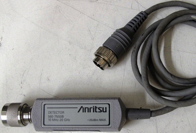
ANRITSU 560-7N50B CALIBRATION and ANRITSU 560-7N50B REPAIR

The ANRITSU 560-7N50B is currently in stock and available for purchase on our  Sales Page
It is also available for immediate rental.
A calibration by Custom-Cal is performed by engineers with extensive OEM experience. We have the expertise and the necessary standards to perform the ANRITSU 560-7N50B Calibration, onsite calibration may be available. We specialize in quick turnaround times and we can handle expedited deliveries upon request.

Need another RF Power Sensor?
Shop for Comparable Products on our
 used RF Power Sensor page

 
   ANRITSU 560-7N50B   Description / Specification:    
ANRITSU 560-7N50B 20 GHz 50 Ohm RF Detector

The Anritsu 560-7N50B RF Detector uses zero-biased Schottky diodes and has a measurement range of -55 dBm to +16 dBm. The detector is used with the Model 56100A and 562 Scalar Network Analyzers and with Series 541XXA, 540XXA, and 54XXA Scalar Measurement Systems for making coaxial transmission loss or gain and power measurements. The detectors are also used with the Site Master and Cable Mate Series Personal SWR/RL and Fault Location Testers for making power measurements. Specifications. Frequency Range: 0.01 to 20 GHz. Impedance: 50 ohm. Return Loss: <0.04 GHz (15 dB), <8 GHz (22 dB), <18 GHz (17 dB), <20 GHz (14 dB). Input Connector: N(m). Frequency Response: ± 0.5 dB (<18 GHz), ± 25 dB (<20 GHz). Maximum Input Power: 100mW (+20 dBm).


Standard Calibration $405.00 *
Click on Logo for More Prices
*This is a Web introductory price for one calibration of the ANRITSU 560-7N50B. Price does not in most cases include measurement performance data. Pricing does include NIST traceable calibration and issue of a calibration certificate and calibration label. Pricing may vary slightly due to volume and location of laboratory supporting calibration. Volume pricing may apply. On-site fees may apply depending on logistics, location and volume of work to be completed during the visit.


Related RF Terms and Definitions. For a complete list go to our  Terms and Definitions Page.

Available Gain
Available Gain is the ratio, at a specific frequency, of power available from the output to the power in from the source.

Frequency Span
Frequency Span specifies the range between the start and stop frequencies, also referred to as bandwidth

Peak Envelope Power
Peak envelope power is the maximum value of the envelope power. Envelope power is measured by making the averaging time much less than 1/fm where fm is the maximum frequency component of the modulation waveform. The averaging time is therefore limited on both ends: (1) it must be small compared to the period of the highest modulation frequency, and (2) it must be large enough to be many RF cycles long.


Please contact us for your ANRITSU 560-7N50B CALIBRATION and/or ANRITSU 560-7N50B 20 GHz 50 Ohm RF Detector REPAIR

I'm interested in: 
Calibration Type (Select one):
Repair Information:
 Serial Number:

 Is there any physical damage?  
 If yes, describe:


What is the description of the problem?

How/when did the problem start?


 (*) Required Fields    For formal quote please fill in all fields.
Company:
From (Email):*
Contact Name:*
Country:*
Address 1:
Address 2:
City:
State/Territory/Province: *
Zip/Postal Code:
Phone:*

Comment: