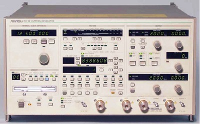
ANRITSU MP1763C REPAIR and ANRITSU MP1763C CALIBRATION

 
Custom-Cal has a high success rate in the repair of the ANRITSU MP1763C. A calibration by Custom-Cal is performed by engineers with extensive OEM experience. We have the expertise and the necessary standards to perform the ANRITSU MP1763C Calibration, onsite calibration may be available. We specialize in quick turnaround times and we can handle expedited deliveries upon request.

Need another Pattern Generator?
Shop for Comparable Products on our
 used Pattern Generator page

 
   ANRITSU MP1763C   Description / Specification:    
ANRITSU MP1763C Pulse Pattern Generator

The Anritsu MP1763C 0.05 to 12.5 GHz Pulse Pattern Generator is used in combination with the MP1764C/1764D Error Detector. The MP1763C Pulse Pattern Generator combined with the MP1764C/1764D Error Detector are a BERTS (Bit Error Rate Test Set) supporting evaluation and testing of transmission equipment, high-speed devices, optical modules, etc., at every stage from R&D through to manufacturing and production at speeds from 50 Mbit/s to 12.5 Gbit/s.
Specifications.
Operation frequency: 0.05 to 12.5 GHz.
Internal CLOCK (Option 01) Frequency range: 0.05 to 12.5 GHz,
Internal CLOCK (Option 01) SSB phase noise: ≤-85 dBc/Hz (0.05 to 4 GHz), ≤-80 dBc/Hz (4 to 8 GHz), ≤-75 dBc/Hz (8 to 10 GHz), ≤-70 dBc/Hz (10 to 12.5 GHz) *At 10 kHz offset, 1 Hz bandwidth
External CLOCK input level: 0.4 to 2.5 Vp-p.

Pattern
Pseudorandom binary sequence pattern (PRBS)
Pattern: 2n - 1 (n: 7, 9, 11, 15, 20, 23, 31)
Mark ratio: 1/2, 1/4, 1/8, 0/8 (1/2, 3/4, 7/8, 8/8 are possible with logic inversion)
Bit shifts number for mark ratio varied: 1, 3 bits selectable
DATA pattern
DATA length: 2 to 8388608 bits
Alternate pattern
A/B pattern DATA length: 128 to 4194304 bits (128 bit steps); Loop time: A, B pattern (1 to 127, 1 steps)
Zero substitution pattern
Zero bit length: 1 to (pattern length - 1) bits; Pattern: 2n (n: 7, 9, 11, 15)
Error addition
Error rate: 10-n Error addition (n: 4, 5, 6, 7, 8, 9), and single error
External error injection: Provided

DATA output
Number of outputs: 2 (DATA/DATA independently)
Amplitude: 0.25 to 2 Vp-p, 2 mV steps
Offset voltage
VOH: -2 to +2 V, 1 mV steps
Display: VOH, VTH or VOL selectable
Rise/fall time: Typical 30 ps (10% to 90% of amplitude)
Pattern jitter: ≤20 psp-p, typical 10 psp-p
Waveform distortion: (0-peak) ≤15% or ≤150 mV whichever is greater
Gating input: Provided
Load impedance: 50 Ω (with back termination)
Connector: APC-3.5

CLOCK output
Number of outputs: 3 (CLOCK 1/CLOCK 1, CLOCK 2)
Amplitude
CLOCK 1/CLOCK 1: 0.25 to 2 Vp-p (2 mV steps)
CLOCK 2: 1 Vp-p
Offset voltage
CLOCK 1/CLOCK 1: VOH -2 to +2 V (1 mV steps)
CLOCK 2: VOH 0 V fixed
Rise/fall time: Typical 30 ps (10% to 90% of amplitude)
Load impedance: 50 Ω (CLOCK 1/CLOCK 1: with back termination)
Connector: CLOCK 1/CLOCK 1: APC-3.5, CLOCK 2: SMA
Delay: ±500 ps (1 ps steps)

Options
MP1763C-01: 12.5 GHz Synthesizer (50 MHz to 12.5 GHz)
MP1763C-03 1/4 speed output
MP1763C-08 1/4 Differential Data Output Function (100 Mbit/s to 3.125 Gbit/s)


Standard Calibration $1,025.00 *
Click on Logo for More Prices
*This is a Web introductory price for one calibration of the ANRITSU MP1763C. Price does not in most cases include measurement performance data. Pricing does include NIST traceable calibration and issue of a calibration certificate and calibration label. Pricing may vary slightly due to volume and location of laboratory supporting calibration. Volume pricing may apply. On-site fees may apply depending on logistics, location and volume of work to be completed during the visit.


Related Communication Terms and Definitions. For a complete list go to our  Terms and Definitions Page.

Bandwidth
Bandwidth is the difference between the upper and lower frequencies in a contiguous set of frequencies within which a fiber optic component, link or network will operate.

Multimode Fiber
Multimode Fiber has a large core (almost always 62.5 microns - a micron is one one millionth of a meter - but sometimes 50 microns) and is used with LED sources at wavelengths of 850 and 1300 nm for short distance, lower speed networks like LANs. Both multimode and singlemode fiber have an outside diameter of 125 microns - about 5 thousandths of an inch - just slightly larger than a human hair.

SDH
Synchronous Digital Hierarchy (SDH) is an international digital telecommunications network hierarchy which standardises transmission around the bit rate of 51.84 megabits per second, which is also called STS-1. Multiples of this bit rate comprise higher bit rate streams. Thus STS-3 is 3 times STS-1, STS-12 is 12 times STS-1, and so on. STS-3 is the lowest bit rate expected to carry ATM traffic, and is also referred to as STM-1 (Synchronous Transport Module-Level 1). The SDH specifies how payload data is framed and transported synchronously across optical fibre transmission links without requiring all the links and nodes to have the same synchronized clock for data transmission and recovery.


Please contact us for your ANRITSU MP1763C REPAIR and/or ANRITSU MP1763C Pulse Pattern Generator CALIBRATION

I'm interested in: 
Calibration Type (Select one):
Repair Information:
 Serial Number:

 Is there any physical damage?  
 If yes, describe:


What is the description of the problem?

How/when did the problem start?


 (*) Required Fields    For formal quote please fill in all fields.
Company:
From (Email):*
Contact Name:*
Country:*
Address 1:
Address 2:
City:
State/Territory/Province: *
Zip/Postal Code:
Phone:*

Comment: